We've launched our new site at www.openlighting.org. This wiki will remain and be updated with more technical information.
Difference between revisions of "Arduino RGB Mixer"
From wiki.openlighting.org
(→Host Software) |
m (→Arduino Software) |
||
| (9 intermediate revisions by 2 users not shown) | |||
| Line 1: | Line 1: | ||
{{Features|free=yes|linux=yes|osx=yes|rdm=yes}} | {{Features|free=yes|linux=yes|osx=yes|rdm=yes}} | ||
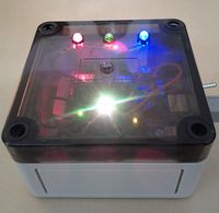
| − | [[Image:Arduino-RGB-RDM.jpg|right|200px]] | + | [[Image:Arduino-RGB-RDM.jpg|thumb|right|200px| The completed RGB mixer, with a RGB led (foreground) on channels 1 - 3 and separate red, green, blue leds (background) on the channels 4 - 6. The led in the middle is used to identify the device.]] |
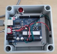
| − | [[Image:Ardunio-RGB.jpg|right|200px]] | + | [[Image:Ardunio-RGB.jpg|thumb|right|200px|The main Arduino board with a sensor and identify led attached]] |
| − | This page describes how to build a 2 LED | + | This page describes how to build a 2 RGB LED (6 channel) color mixer using an [[Arduino]] and [[OLA]] and [[QLC]]. The Arduino is programed to emulate a [[DMX USB Pro]] and implements the [[USB Protocol Extensions]] along with [[RDM]]. You can either use it with single leds like in the diagram or, if you add an additional driver circuit, a set of leds like what you can buy from ikea. |
=== Features === | === Features === | ||
| − | * Six channel PWM controller (multiple personalities enable | + | * Six channel PWM controller (multiple personalities enable inverting the output if needed) |
| − | * DMX Address and Device | + | * DMX Address and Device Label can be set using RDM |
* Identify led (useful when multiple devices are in use so you can identify which device is which) | * Identify led (useful when multiple devices are in use so you can identify which device is which) | ||
* Power cycle counter | * Power cycle counter | ||
| Line 16: | Line 16: | ||
=== Parts === | === Parts === | ||
| − | + | For the basic RGB Mixer you need the following: | |
| − | + | ||
* An [[Arduino]], I used the [http://arduino.cc/en/Main/ArduinoBoardDuemilanove Duemilanove] - $30 | * An [[Arduino]], I used the [http://arduino.cc/en/Main/ArduinoBoardDuemilanove Duemilanove] - $30 | ||
| − | |||
* A 110ohm resistor (or 100 + 10 ohm) to disable the auto-reset on the new Arduino boards. | * A 110ohm resistor (or 100 + 10 ohm) to disable the auto-reset on the new Arduino boards. | ||
* A LM35DZ temperature sensor - $2 | * A LM35DZ temperature sensor - $2 | ||
* A LED to indicate the device is in identify mode - 50c | * A LED to indicate the device is in identify mode - 50c | ||
| + | * Some LEDs and resistors, should be at most a few dollars depending on what you buy. | ||
| − | + | If you want to control banks of lights, you'll also need: | |
| − | + | * LED strip lights, Ikea has a set which are reasonably cheap and come with mounting brackets: [http://www.ikea.com/us/en/catalog/products/50119407 Dioder] - $50 | |
| + | * A power supply for the led lights, make sure it can provide enough current for the amount of leds you plan to use. You can use the one from the Ikea lights. | ||
| + | * Parts to make a driver circuit: 3 x 2N2222 transistors, 3x 2.2k resistors, small PCB - $10 | ||
| − | + | The Ikea leds run from 12V and draw ~420mA when all colors are on so you need to make sure the driver circuit and power supply is sized correctly. | |
| − | + | ==Hardware== | |
| − | |||
| − | |||
| − | |||
| − | |||
=== Identify LED === | === Identify LED === | ||
| Line 47: | Line 45: | ||
The newer Ardiuno boards auto-reset when the serial connection is established which causes problems with OLA. To disable the auto-reset connect a 110 ohm resistor between the RESET and 5V pins. Note that you need to remove this when you program your Arduino. In the picture above a switch is used for ease of programming. | The newer Ardiuno boards auto-reset when the serial connection is established which causes problems with OLA. To disable the auto-reset connect a 110 ohm resistor between the RESET and 5V pins. Note that you need to remove this when you program your Arduino. In the picture above a switch is used for ease of programming. | ||
| + | |||
| + | === LED Driver === | ||
| + | |||
| + | The LEDs use 12V while the Arduino supplies 5V so we need to make a driver circuit. The one below should be good up to 600mA per channel or so. | ||
| + | |||
| + | [[Image:RGB-arduino-driver.png|center]] | ||
| + | |||
| + | You need one of these per channel. The inputs should be connected to the PWM pins on the Arduino (pins 3, 5, 6, 9, 10, 11 on a Duemilanove). Make sure you connect the ground of both circuits. | ||
== Arduino Software== | == Arduino Software== | ||
| Line 53: | Line 59: | ||
<pre> | <pre> | ||
| − | git clone https:// | + | git clone https://github.com/OpenLightingProject/rgbmixer.git arduino-rgb-mixer |
</pre> | </pre> | ||
| − | To build the sources you'll need the Arduino development environment | + | To build the sources you'll need the Arduino development environment which can be found at http://arduino.cc/en/Main/Software. Edit the Makefile and adjust the path to your Arduino installation (INSTALL_DIR) . You may also need to change the USB port path (PORT) and board specific parameters like UPLOAD_RATE, AVRDUDE_PROGRAMMER & MCU if you're using different hardware. |
| + | |||
| + | To build and upload the software to your Arduino run: | ||
| + | |||
| + | <pre> | ||
| + | make | ||
| + | make upload | ||
| + | </pre> | ||
| − | + | If you don't want to build from source, the latest compiled version of the firmware is available at https://github.com/OpenLightingProject/rgbmixer/releases | |
== Host Software== | == Host Software== | ||
Latest revision as of 18:35, 1 March 2014
{{ #if: yes | ![]() }}{{ #if: |
}}{{ #if: | ![]() }}{{ #if: yes |
}}{{ #if: yes | ![]() }}{{ #if: yes |
}}{{ #if: yes | ![]() }}{{ #if: |
}}{{ #if: | ![]() }}{{ #if: |
}}{{ #if: | ![]() }}{{ #if: yes |
}}{{ #if: yes | ![]() }}{{ #if: |
}}{{ #if: | ![]() }}{{ #if: |
}}{{ #if: | ![]() }}
}}
This page describes how to build a 2 RGB LED (6 channel) color mixer using an Arduino and OLA and QLC. The Arduino is programed to emulate a DMX USB Pro and implements the USB Protocol Extensions along with RDM. You can either use it with single leds like in the diagram or, if you add an additional driver circuit, a set of leds like what you can buy from ikea.
Contents
Features
- Six channel PWM controller (multiple personalities enable inverting the output if needed)
- DMX Address and Device Label can be set using RDM
- Identify led (useful when multiple devices are in use so you can identify which device is which)
- Power cycle counter
- Optional Temperature Sensor
- Serial number (UID) can be set remotely
Parts
For the basic RGB Mixer you need the following:
- An Arduino, I used the Duemilanove - $30
- A 110ohm resistor (or 100 + 10 ohm) to disable the auto-reset on the new Arduino boards.
- A LM35DZ temperature sensor - $2
- A LED to indicate the device is in identify mode - 50c
- Some LEDs and resistors, should be at most a few dollars depending on what you buy.
If you want to control banks of lights, you'll also need:
- LED strip lights, Ikea has a set which are reasonably cheap and come with mounting brackets: Dioder - $50
- A power supply for the led lights, make sure it can provide enough current for the amount of leds you plan to use. You can use the one from the Ikea lights.
- Parts to make a driver circuit: 3 x 2N2222 transistors, 3x 2.2k resistors, small PCB - $10
The Ikea leds run from 12V and draw ~420mA when all colors are on so you need to make sure the driver circuit and power supply is sized correctly.
Hardware
Identify LED
RDM allows a device to be put into 'identify mode'. The RGB Mixer uses an LED to indicate when identify mode is enabled. This LED should be connected between pins 12 and ground.
Temperature Sensor
The output of the LM35 should be connected to analog pin 0 as shown on http://www.danielandrade.net/2008/07/05/temperature-sensor-arduino/
Disable Auto-Reset
The newer Ardiuno boards auto-reset when the serial connection is established which causes problems with OLA. To disable the auto-reset connect a 110 ohm resistor between the RESET and 5V pins. Note that you need to remove this when you program your Arduino. In the picture above a switch is used for ease of programming.
LED Driver
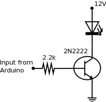
The LEDs use 12V while the Arduino supplies 5V so we need to make a driver circuit. The one below should be good up to 600mA per channel or so.
You need one of these per channel. The inputs should be connected to the PWM pins on the Arduino (pins 3, 5, 6, 9, 10, 11 on a Duemilanove). Make sure you connect the ground of both circuits.
Arduino Software
The sources can be downloaded by running
git clone https://github.com/OpenLightingProject/rgbmixer.git arduino-rgb-mixer
To build the sources you'll need the Arduino development environment which can be found at http://arduino.cc/en/Main/Software. Edit the Makefile and adjust the path to your Arduino installation (INSTALL_DIR) . You may also need to change the USB port path (PORT) and board specific parameters like UPLOAD_RATE, AVRDUDE_PROGRAMMER & MCU if you're using different hardware.
To build and upload the software to your Arduino run:
make
make upload
If you don't want to build from source, the latest compiled version of the firmware is available at https://github.com/OpenLightingProject/rgbmixer/releases
Host Software
Download and install OLA (verion 0.8.9 or above) and QLC if you want a graphical frontend. See the documentation for either/both products for getting it installed. The device should show up as a DMX USB Pro, the first three channel control the red, green & blue intensities.
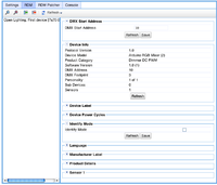
The image below shows the RDM settings page in OLA for this device.
Future Work
- Expand the PWM outputs with http://www.arduino.cc/playground/Learning/TLC5940


